Inverted Power Rail
Attempt 1: LT1931 #
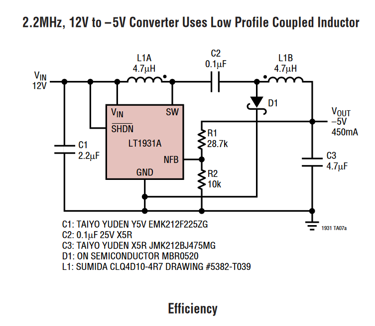
i initially tried to tackle the -8V power rail first. after some intense searching on the internet, i stumbled across the LT1931. i thought that this would be a good choice to do some testing with (it wasn’t) as it seemed like a very small package capable of delivering enough current to meet my requirements - the LT1931 advertises a 1A switching current, even at 50% duty cycle this should be enough to deliver my desired 400mA.
there was one circuit configuration in particular that stood out to me - it was almost exactly what i needed!
LT1931 Calculations #
i calculated the circuit to provide a -8V output and searched for some components to suit the newly calculated values. unfortunately i don’t have the exact components and calculations on hand but perhaps i’ll consider redoing this at some other point.
LT1931 Assembly #
i ordered some of the LT1931 ICs and the components to suit, and some SOT-23 break-out PCBs suitable for use on a solderless breadboard (i think this was my first mistake). i didn’t design a PCB for this at this point in the project as i had never done PCB design before, nor was i ready to try and take a leap into the deep end. for context, this was the first piece of electronics design i had delved into in a good 2-3 years.
once everything had arrived i constructed the circuit on my breadboard and unfortunately observed no useful output. in fact, i tried with 3 different LT1931 ICs, 4 different solderless breadboards, and 3 sets of components all to no avail. i was quite stumped as to why this might not have been working, but for now i decided to take a break on this design. i did consider coming back to this IC at a later date but they are quite costly and not abundantly available - so that is the end of this attempt.
Attempt 2: LM46002 #
the next IC that caught my eye was the texas instruments (TI) LM46002. while this didn’t advertise an inverting configuration, i found some resources ( a report and a video from TI). from these resources, it seemed the LM46002 demonstrates some promising properties of the IC, and appeared to be aligned with my design requirements.
Inverting circuit and calculations #
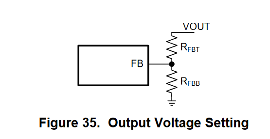
the LM46002 sets the output voltage using a voltage divider set with a feedback voltage. the configuration can be seen in the image below.
where;
- $R_{FBT}$ is the top feedback resistor
- $R_{FBB}$ is the bottom feedback resistor
- $FB$ is the feedback voltage pin
the datasheet defines the relationship between the output voltage $V_{out}$ and the feedback resistors as follows. $$ \begin{align} R_{FBB} = \frac{V_{FB}}{V_{out} - V_{FB}} R_{FBT} \end{align} $$ where $V_{FB}$ is the feedback voltage (typically 1.011V).
for revision A, i chose the values of $R_{FBT} = 68k\Omega$ and $R_{FBB} = 10k\Omega$. if we rearrange the equation to solve for $V_{out}$, we get the following;
$$ \begin{align*} V_{out} &= \frac{R_{FBT}}{R_{FBB}}V_{FB} + V_{FB} \\ &= \frac{68k\Omega}{10k\Omega}\times1.011V + 1.011V \\ &= (6.8 \times 1.011) + 1.011 \\ &= 7.89V \end{align*} $$
for revision B, the values i chose were as follows.
PCB Design; Revision A #
my first approach was to design the same circuit used in the resources previously mentioned onto a PCB - as an attempt to get something happening. the below images are my first revision of the LM46002 PCB.
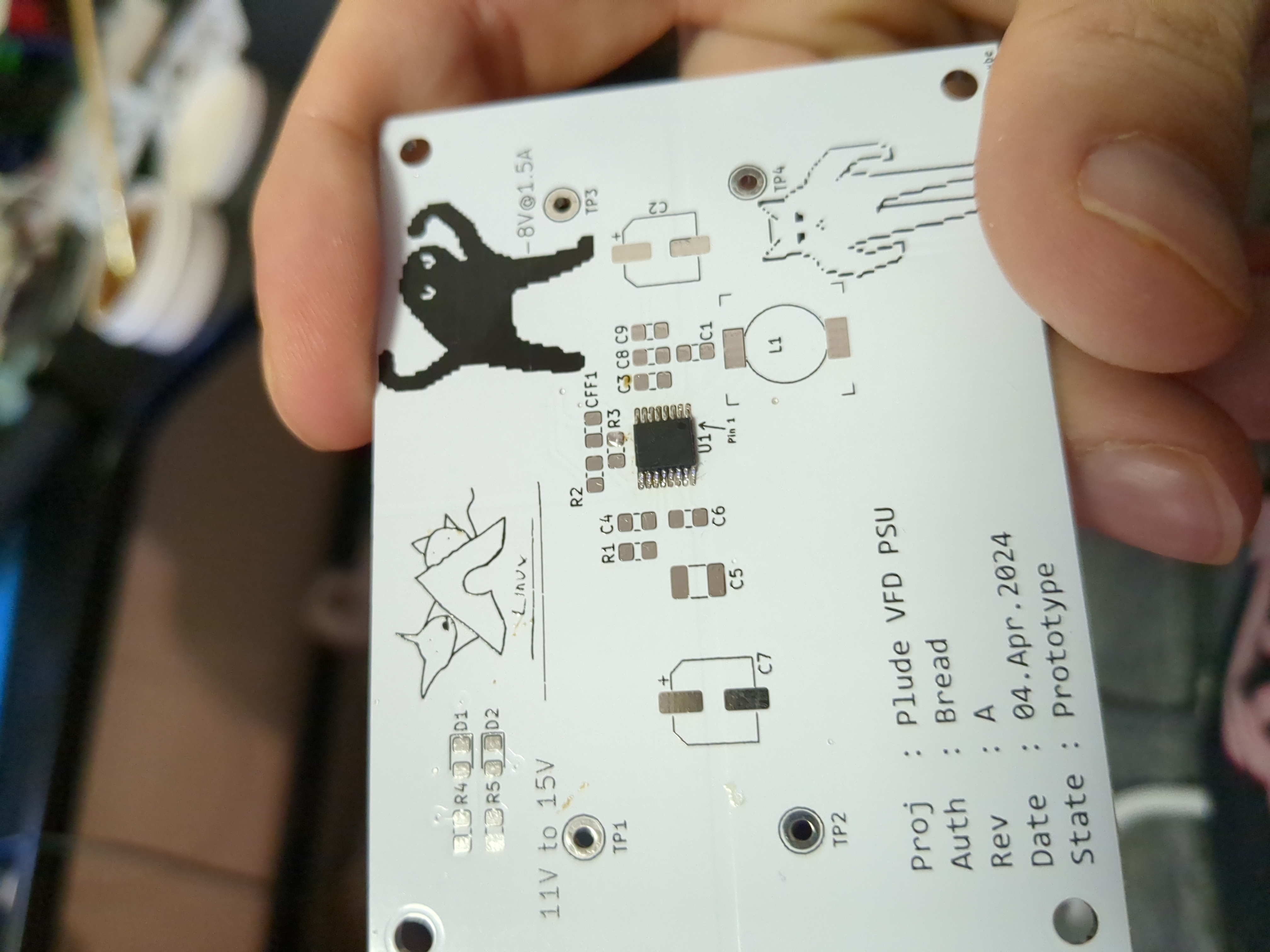
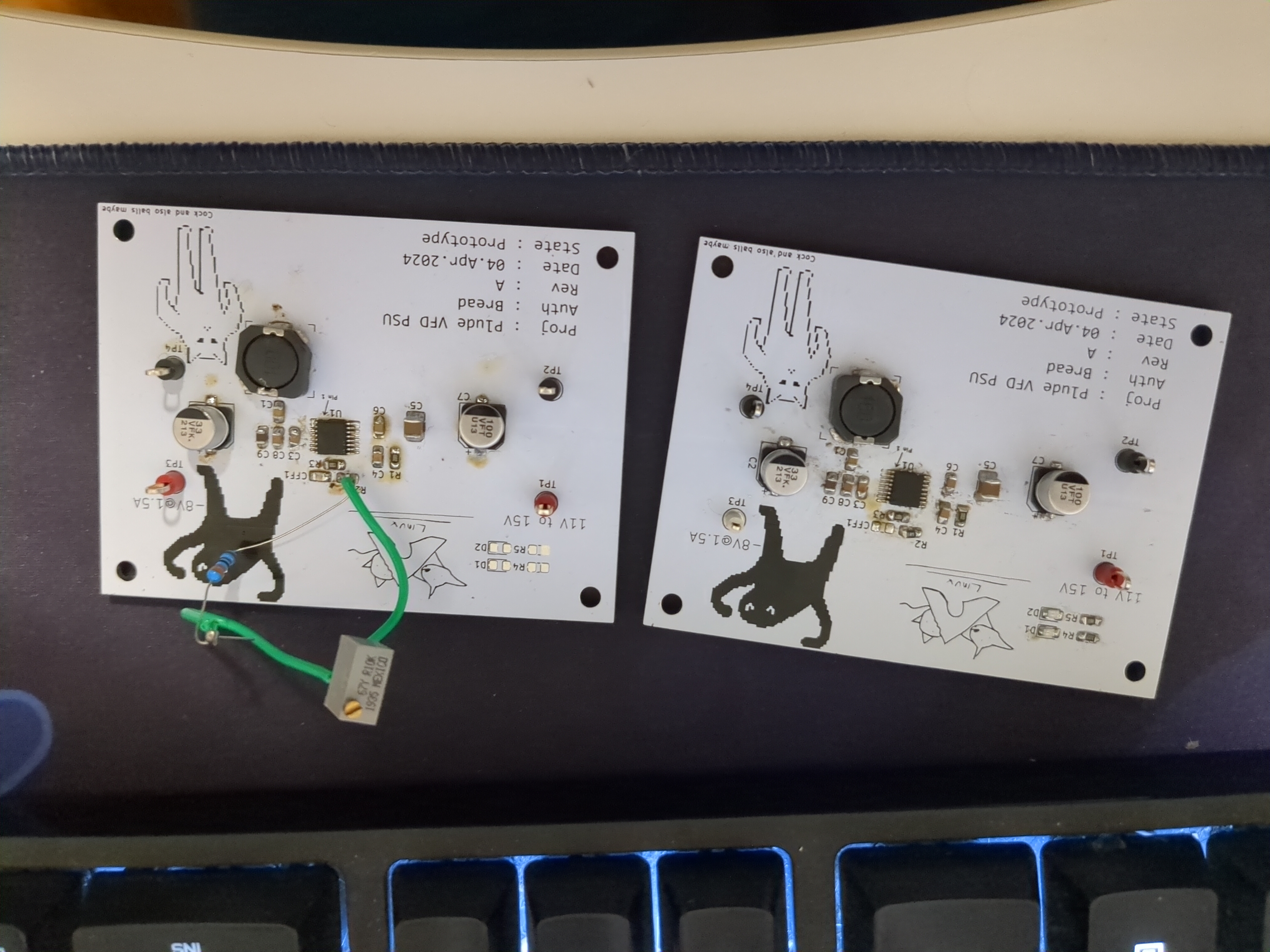 these boards did appear to function, but not at the -8V value as intended (despite my calculations). i even tried to solder a potentiometer in-line as an attempt to adjust the output value (something i wish i did in this design anyway). for some reason, these boards would provide approx. -20V at the output.
there appears to be a common theme here; either i’m bad at maths, or the datasheets are incorrect (i’m probably bad at maths). since starting revision B of the LM46002 PCB, i went back to this revision to attempt to revise and review the inverted rail design but they all stopped working (as of 28/May/2024). more to come on that at some point. for now, i’d rather work with a solution that is already existing and reliable enough, which is where the third attempt comes in (LM2596).
Attempt 3: LM2596, LMR33030 and LMR14020 #
i found this super super interesting video which may appear to solve my problems for this (and allow me to progress with the alternating voltage signal). i have ordered some of the cheap modules from AliExpress to test while i awaited PCBs to arrive for the H-Bridge testing. however, all modules seemed to explode when wiring into the configuration shown in the video. my guess is the modules use face ICs and they aren’t designed to deal with an inverting circuit topology. instead, i will design a PCB that encompasses a few different ICs to evaluate all of them in one go.
i chose the LM2596 due to the aforementioned video, and the LMR33030 and the LMR14020 due to this document made by TI.
LM2596 #
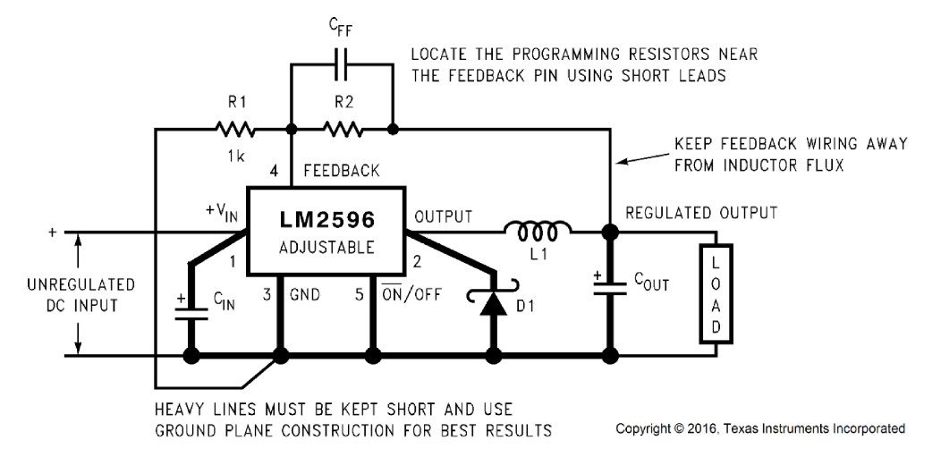
$$ \begin{align} V_{out} &= V_{ref} \left( 1 + \frac{R_2} {R_1} \right) \\ \\ V_{ref}&=1.23 \textup{V} , \\ \\ R_1 = 1 \textup{k} \ohm \\ \\ R_2 &= R_1 \left( \frac{V_{out}}{V_{ref}} - 1\right) \\ \\ C_{FF} &= \frac{1}{(31)(10^3)(R_2)} \\ \
& \textup{for } V_{out} \textup{ = -5V} \\ R_2 &= 1\textup{k} \left( \frac{5}{1.23} - 1\right) = 3.065\textup{k}\ohm \\ C_{FF} &= \frac{1}{(31\textup{k})(3.065\textup{k})} = \frac{1}{95.015\textup{M}}=10\textup{nF}\\ \
& \textup{for } V_{out} \textup{ = -12V} \\ R_2 &= 1\textup{k} \left( \frac{12}{1.23} - 1\right) = 8.756\textup{k}\ohm \\ C_{FF} &= \frac{1}{(31\textup{k})(8.756\textup{k})} = \frac{1}{271.436\textup{M}}=3.7\textup{nF}\\ \
\end{align} $$
from the Inverting Buck Boost document;
LMR33640; #
$$ \begin{align} L &= \frac{V_{in}}{F_s \\ \Delta I_L} \frac{|{V_{out}|}}{V_{in} \\ \eta \\ + \\ V_{out}}\\ \Delta I_L &= 30% \times0.5 \textup{A}=0.15 \textup{A} \\ , \\ \\ \eta = 85% \\ , \\ V_{in} = 14\textup{V} \\ , \\ F_s = 400\textup{kHz}\\ \
\textup{For -5V} & \\ , V_{in} = 14 - - 5 = 19\\ L &= \frac{19}{400\textup{k} \times 0.15} \frac{5}{(19 \times 0.85) - 5} = 69\mu H \approx 68\mu H \\ \\ \
\textup{For -11V} & \\ , V_{in} = 14 - - 11 = 25\\ L &= \frac{25}{400\textup{k} \times 0.15} \frac{11}{(25 \times 0.85) - 11} = 112\mu H \approx 150\mu H
\end{align} $$
LMR14020 #
switching freq = 400kHz